dnv

BOP Accumulator Units


Sara's BOP Accumulator Units meet or exceed the design specification as specified in API 16D. Each control system is specifically engineered to assure reliable control of the BOP stack with adequate reserve for continuous operation under emergency conditions. Sara welcomes the opportunity to assist you in the proper selection of standard equipment or custom design to meet your application and certification requirements.

Model Number Identification System

BOP Accumulator Units
This system shown here is for Air Remote Control Panel operation. Sara systems that are designed to meet API 16D must have Air-Electric Remote Control Panels if they are used on Offshore Drilling Rigs.

Control Systems for Diverter Equipment

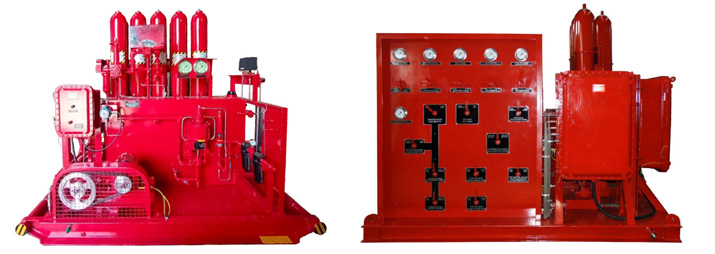
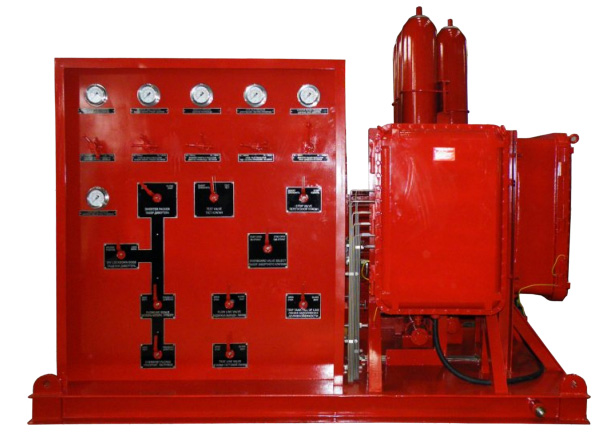
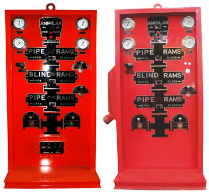
The diverter master panel controls the flowline seals, manifold functions, and diverter packer, which contains and directs wellbore pressure away from the drill floor. The pressure may consist of oil, gas, or water-cut mud, all of which must be diverted to a harmless area.

The diverter master panel has hydraulically-operated functions, air-operated functions, and an air-operated pressure regulator. The hydraulic pressure for the hydraulic functions is provided by the accumulator unit. The air-operated functions and regulators are supplied with rig instrument air.

All diverter functions can be operated from the diverter master panel or remotely from the driller’s control panel and the toolpushrer’s control panel.

Sara Sae Manufacture different type of Diverter:- MSPType, KFDJ Type others

Sara Sae welcomes the opportunity to assist you in the proper selection of standard equipment or custom design to meet your application and certification requirements.

Diverter Equipment

HCR Panel

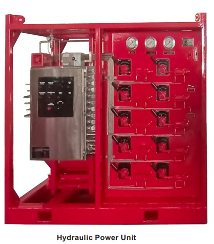
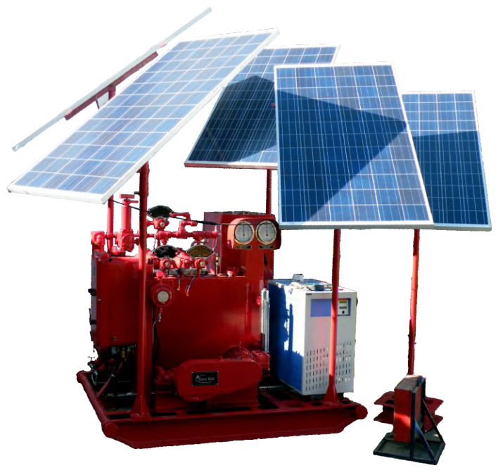
Sara Sae's HCR Panels is a high pressure fitted with directional control valves to provide hydraulic power to operate gate valve. The Hydraulic Power Unit is a skid mounted assembly consisting of fluid storage tank, control valves, regulators and various control components. Sara Sae welcomes the opportunity to assist you in the proper selection of standard equipment or custom design to meet your application and certification requirements.

Hydraulic Power Unit

Shear Boost system of BOP

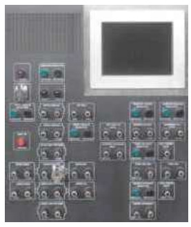
A Shear Boost of Blowout Preventer (BOP) Control System is a high pressure hydraulic power unit fitted with directional control valves to boost the shear pressure to safely control kicks and prevent blowouts during drilling operations. The Shear Boost System is mounted on BOP control unit and consisting of fluid storage tank, hydraulic pumps, control valves, regulators and various control components. The Shear Boost System provides pressurized fluid for the Shear Boost system using the electric driven hydraulic triplex pumps & Air Pumps. Hydraulic pressure from all the pumps is stored in the accumulator bottles mounted on the separate mounted skid. The accumulator bottles have a working pressure of 5,000 psi (352 Kg/Cm Sq.) dedicated to the Shear Boost system.

Shear Boost system

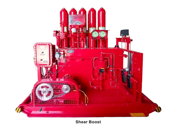
In addition to the above, Shear Boost valves is also Operated by electric remote control panel. It should be noted the Electric Operated remote panel does not interfere with the manual operation of the control valves at the Shear Boost System. The valves may be remotely operated at the Electric Operated remote control panel or manually at the Shear Boost System. Sara Sae welcomes the opportunity to assist you in the proper selection of standard equipment or custom design to meet your application and certification requirements.

Remote Panels

 Remote Panels 1
System Configuration
 Remote Panels 2
Alarm Logs and Pressure Trends
 Remote Panels 3
System Setting

Air Remote Panels

Air Remote Panels control rig air pressure to the hydraulic control manifold to operate the manifold functions. An air interface module is required on the accumulator unit and an air interconnect is required to connect the air remote panel to the interface module. Air remote offered in several standard models to meet usual requirements and are available for any special application upon request. Air-electric panels additionally have explosion proof light stations for each BOP stack function (bypass/ internal override included, when applicable) to indicate open or close status of the hydraulic control manifold valves.

PLC Panel with Touchscreen Display

  • Programmable Logic Controls (PLC) based system
  • LCD color touchscreen provides pressure readout
  • Electrical indication lights for valve position
  • Audible and visual alarm for low system pressure, low rig-air and low reservoir fluid level.
  • 24 VDC electrical backup
  • Wireless and wired configurations
  • Logs, functions, and alarms

Features

  • Explosion proof for Class I Div. I or Class I Div. II
  • Air cooler for higher temperatures
  • Logging of functions and alarms
  • Air and battery back up
  • Minimum rig-up time; no air hose
  • Printer port for report generation
PLC Panel

Functions

  • Visual indications of valve position
  • Audible and visual alarm for low accumulator pressure, low manifold pressure, low rig air pressure and low reservoir fluid level
  • Push buttons from open/close function with master push button for two hand operation
  • Push buttons for high/low function of bypass valve
  • Push buttons for raise/lower annular regulator pressure setting
  • Push button for lamp test

Options

  • Wireless modem for remote communications allows unit status to be monitored remotely
  • Communication via optic fiber cable
  • Sunlight viewable screen
Remote panel wireless

Solar Control Systems for Land Based and Surface-Mounted BOP Stacks

Salient Features

  1. Can run both on Solar PV power & Grid Power.
  2. Easy to operate, useful for rigs in remote areas.
  3. Smart Inverter to prioritize PV power over Grid.
  4. Protection against overloading, under voltage, phase imbalance, cut cable.
  5. Provided with battery backup sufficient to charge accumulator 5 times in a day.
  6. Adjustable & Removable high efficiency solar Panel mounted on the unit itself.
  7. 3 HP motor with robust Pump supported by Maximum power point tracker for fail safe operation.
  8. Single time investment with negligible running cost.

Technical Specification

  • Fluid Reservoir Capacity : 30 Gallons
  • Operating Temperature : Mild, Tropical (-40° to 60° Deg<)
  • Accumulator Capacity : 4 X 2.5 Gallons
  • Pumping Capacity : 4.5 GPM @ 3000 PSI
  • Pipe Line : SCH 160
  • Batter Bank : 2 Sets of 400AH Gel based C10 rated
  • Alternate Hand Pump module for Manual operation.
  • Compliant to ASME U-1A, API 16D
Solar Remote Panel

RT138 – For Workover Rig

1. Description

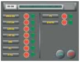
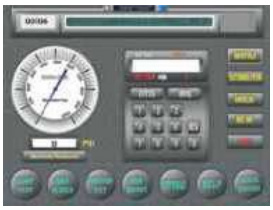
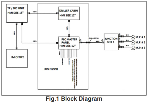
A Workover Rig Monitoring System (RT138) is a comprehensive solution designed to monitor and optimize the operations of workover rigs, which are essential in the oil and gas industry for well intervention and maintenance. This monitoring system leverages advanced technology and data analysis to enhance the safety, efficiency, and productivity of workover rig operations. The RT138 system typically consists of sensors, data acquisition devices, communication infrastructure, and software applications. These components work together to collect real-time data from various aspects of the workover rig, including hydraulic systems, power units, drilling fluid parameters, and overall rig performance. The collected data is transmitted to a centralized control centre or a digital platform (HMI), where it is processed, analysed, and visualized in a user-friendly format. Operators, supervisors, and engineers can access this information to gain valuable insights into the rig's performance, identify any operational issues or anomalies, and make data-driven decisions to optimize rig operations.

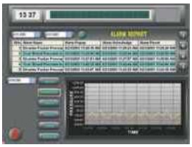
The workover rig monitoring system offers several key benefits. Firstly, it improves safety by continuously monitoring critical parameters such as weight on bit, hook load, wellbore pressures, toxic & combustible gas and fluid levels, thereby helping to prevent accidents and equipment failures. It also enables proactive maintenance by detecting early signs of equipment wear or malfunction, allowing for timely repairs and reducing downtime.

Furthermore, the system enhances operational efficiency by providing real-time performance metrics, allowing operators to optimize drilling parameters, adjust equipment settings, and make informed decisions to increase overall productivity. It also facilitates better resource allocation and scheduling by providing visibility into the utilization of rig assets and personnel. Additionally, the workover rig monitoring system enables remote monitoring and control, reducing the need for personnel to be physically present onsite. This capability is particularly valuable in remote or hazardous environments, as it minimizes risks and improves operational flexibility.

Overall, a workover rig monitoring system is a powerful tool that enables real-time monitoring, analysis, and optimization of workover rig operations. By leveraging datadriven insights, it helps improve safety, efficiency, and productivity, leading to cost savings and enhanced performance in the oil and gas industry.

2. System Architecture

The Workover Rig Monitoring System consists of several interconnected components. These include:

  • Sensors and Data Acquisition: Various pressure sensors, Flow & Level Sensors, Gas detection sensors, are strategically placed throughout the rig to collect data on key parameters such as hook load, fluid pressures, temperatures, H2S & HC detectors. Data acquisition devices capture this information and transmit it to a central hub for processing.
  • PLC System & Communication Infrastructure: The sensors installed on the BOP Control Unit talk to a PLC based system. The PLC system acquires raw signal from the sensors and conditions it in a format which is understandable by the RT138 local system. The system relies on a robust communication infrastructure, to transmit data from the rig to the central monitoring station (HMI). This ensures timely and seamless data transfer.
  • RT138 Central Monitoring and Control: At the heart of the system, a centralized monitoring station receives, processes, and analyses the data. This station is equipped with powerful software applications that provide real-time visualization, analytics, and control capabilities. The RT138 System is a standalone unit that is installed on the Rig Side and talks to the PLC system described above. This system captures the processed sensor data from the PLC unit and displays it in an intuitive UI format. The system samples and logs all the data at a rate of 1Hz and is capable of maintaining a continuous log of up to 5 years.
  • Visualization and User-Interface: The monitoring system includes user-friendly visualization tools and a graphical user interface (GUI) that display the real-time rig data and analysis results. These visualizations can include interactive dashboards, charts, graphs, and alarms to provide operators with a comprehensive overview of the rig's performance and status.

 Block Diagram

Registered Office

Sara Sae Private Limited
E-30, Anand Niketan (Basement), New Delhi - 110021, Delhi, India, +91-7648969696, ssae@sarasae.com
CIN: U74899DL1980PTC010317

INDIA

Sara Sae Private Limited
9RGH+9X6, Selaqui Rd, Shankarpur,
Dehradun,
248197 Uttarakhand, India
+91-7648969696
ssae@sarasae.com

USA

STS Products, Inc.
713.502.3460
sts@stsproductsinc.com

Consolidated Pressure Control
713.502.3460
sales@cpcmfg.com

DUBAI

STS PRODUCTS FZE
Office No 1165, 11th floor,
JAFZA ONE BUILDING, TOWER A
Jebel Ali (North), Dubai, UAE
Tel - 971(0) 48170234

United Arab Emirates

Sara Services and Engineers LLC
Sharjah Media City Building Sharjah,
Post Box No. 515000, UAE

SARA SAE Machines & Spare Parts Trading - LLC
AL Dana East 06 – Omar Otaiba,
Abdullah Ahmed Building
Abu Dhabi
©2011 Sara Sae India Pvt Ltd. All rights reserved
Powered by: Fylfot Software